A 36-key monoblock split keyboard with three thumb keys on each side.

Lorem Ipsum 36? Dolor Sit Amet Keyboard!

You know, it’s a tale as old as custom mechanical keyboards. [penkia] couldn’t find any PCBs with 36 keys and Gateron low-profile switch footprints, so they made their own and called it the LoremIpsum36. Isn’t it lovely?

Close-up of the RP2040 sitting flush as can be in the PCB.
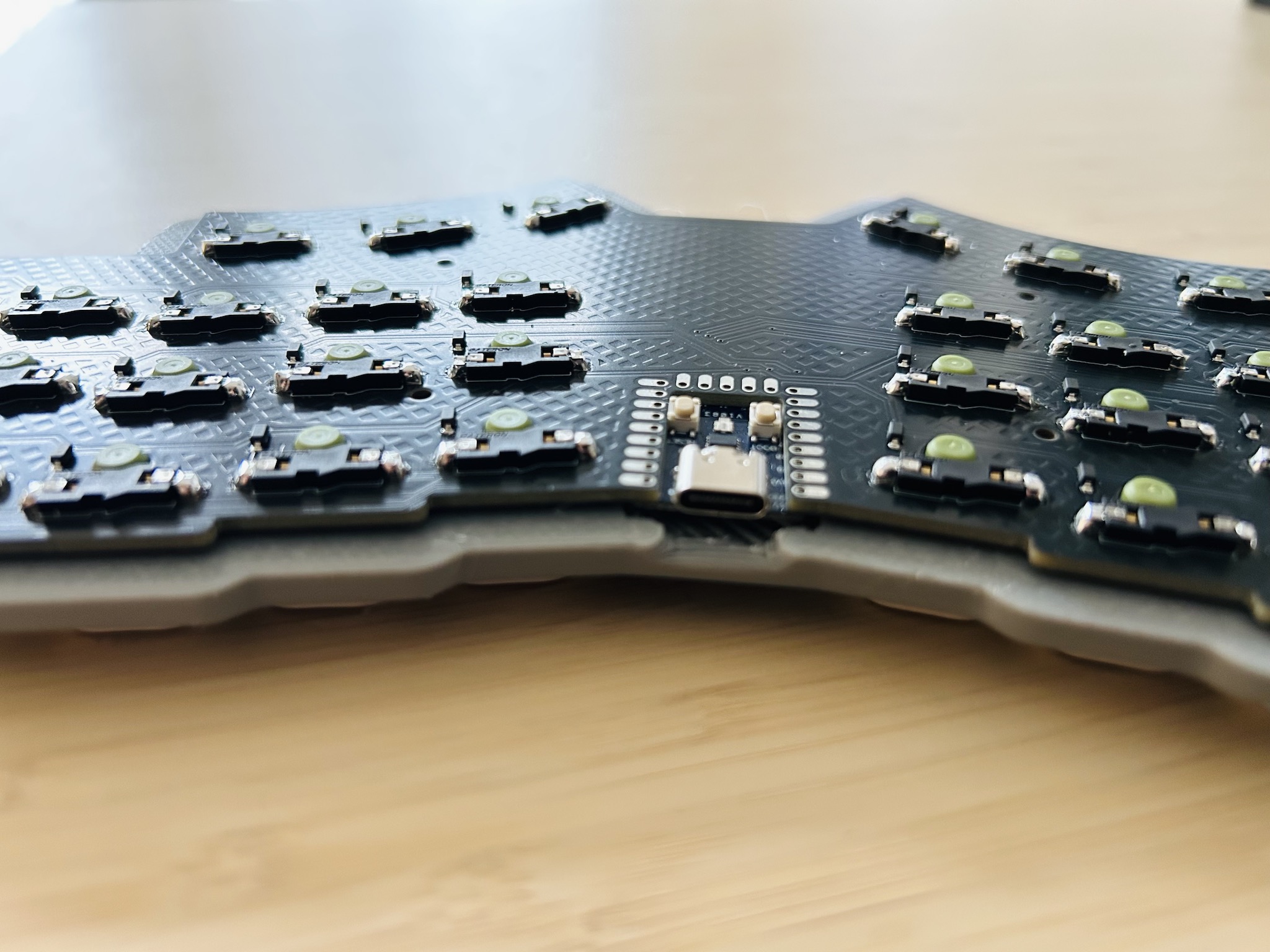
This baby runs on an RP2040, which sits flush as can be in a cutout in the PCB. This maneuver, along with the LP switches in hard-to-find SK-33 sockets results in quite the thin board.

[penkia] says that despite using a 3 mm tray for added rigidity, the entire thing is thinner than the Nuphy Air60 v2, which is just over half an inch (13.9 mm) thick. For keycaps, [penkia] has used both XVX profile and FKcaps’ LPF.

And yeah, that area in the middle is crying out for something; maybe a trackball or something similar. But [penkia] is satisfied with it as-is for the first version, so we are, too.

Do you like 36-key boards, but prefer curves? Check out the Lapa keyboard, which doubles as a mouse.

A Raspberry Pi HAT with retro LED displays and a buttons, sitting on the keys of a laptop.

Good-Looking HAT Does Retro Displays Right

Mick Jagger famously said that you cain’t always get what you want. But this is Hackaday, and we make what we want or can’t get. Case in point: [Andrew Tudoroi] is drawn to retro LEDs and wanted one of Pimoroni’s micro-LED boards pretty badly, but couldn’t get his hands on one. You know how this ends — with [Andrew] designing his first PCB.

The Pitanga hat is equally inspired by additional fruit that [Andrew] had lying around in the form of an 8devices Rambutan board. (Trust us, it’s a fruit.) With some research, he discovered the HT16K33 LED driver, which checked all the boxen.

Pitanga hats with various cool LED displays.The first version worked, but needed what looks like a couple of bodge wires. No shame in that! For the next revision, [Andrew] added buttons and decided to make it into a Raspberry Pi HAT.

This HAT is essentially a simple display with a basic input device, and a beauty at that. You can see all the various cool displays that [Andrew] tried both here and in the project log. Although he included pads for an ARM M0 microcontroller, he never did populate it. Maybe in the future.

Of course, this project was not without its challenges. For one thing, there was power compatibility to wrestle with. The Pi can sometimes work with I²C devices at 5 V, but this isn’t ideal long-term. So [Andrew] put the LED driver on the 3.3 V I²C bus. Despite the data sheet calling for 4.5 to 5.5 V, the setup worked fine. But for better reliability, [Andrew] threw a dedicated I²C logic level converter chip into the mix.

Don’t forget, you can run a noble amassment of HATs with the PiSquare.

JTAG & SWD Debugging On The Pi Pico

[Surya Chilukuri] writes in to share JTAGprobe — a fork of the official Raspberry Pi debugprobe firmware that lets you use the low-cost microcontroller development board for JTAG and SWD debugging just by flashing the provided firmware image.

We’ve seen similar projects in the past, but they’ve required some additional code running on the computer to bridge the gap between the Pico and your debugging software of choice. But [Surya] says this project works out of the box with common tools such as OpenOCD and pyOCD.

As we’ve cautioned previously, remember that the Pi Pico is only a 3.3 V device. JTAG and SWD don’t have set voltages, so in the wild you could run into logic levels from 1.2 V all the way to 5.5 V. While being able to use a bare Pico as a debugger is a neat trick, adding in a level shifter would be a wise precaution.

Looking to get even more use out of those Pi Picos you’ve got in the parts bin? How about using it to sniff USB?

All The Attacks On The RP2350

Raspberry Pi’s new microcontroller, the RP2350, has a small section of memory that is meant for storing secrets. It’s protected by anti-glitching and other countermeasures, and the Raspberries wanted to test it. So this summer, they gave them out, pre-programmed with a secret string, as part of the badge for DEFCON attendees. The results of the cracking efforts are in, and it’s fair to say that the hackers have won.

First place went to [Aedan Cullen], who also gave a great talk about how he did it at 38C3. One of the coolest features of the RP2350, from a hacker perspective, is that it has dual ARM and dual RISC-V cores onboard, and they can be swapped out by multiplexers. The security module has a critical register that has disable bits for both of these processors, but it turns out that the ARM disable bits have priority. When [Aedan] glitched the security module just right, it disabled the ARM cores but left the RISC-V cores running in the secure context, with full debug(!), and the game was over. As of yet, there is no mitigation for this one, because it’s baked into the secure boot module’s silicon.

[Marius Muench] managed to pre-load malicious code into RAM and glitch a reboot-out-of-secure-mode on the USB module. This one is possibly fixable by checking other reboot flags. [Kévin Courdesses] has a sweet laser fault-injection rig that’s based on the 3D-printable OpenFlexure Delta Stage, which we’ve seen used for microscopy purposes, but here he’s bypassing the anti-glitching circuitry by exposing the die and hitting it hard with photons.

Finally, [Andrew Zonenberg] and a team from IOActive went at the RP2350 with a focused ion beam and just read the memory, or at least the pairwise-OR of neighboring bits. Pulling this attack off isn’t cheap, and it’s a more general property of all anti-fuse memory cells that they can be read out this way. Chalk this up as a mostly-win for the offense in this case.

If you want to read up on voltage glitching attacks yourself, and we promise we won’t judge, [Matthew Alt] has a great writeup on the topic. And ironically enough, one of his tools of choice is [Colin O’Flynn]’s RP2040-based Chip Shouter EMP glitcher, which he showed us how to make and use in this 2021 Remoticon talk.

Logging Baby’s Day In Linux

There’s plenty of surprises to be had when you become a parent, and one of the first is that it’s suddenly your job to record  the frequency of your infant’s various bodily functions in exacting detail. How many times did the little tyke eat, how long did they sleep, and perhaps most critically, how many times did they poop. The pediatrician will expect you to know these things, so you better start keeping notes.

Or, if you’re [Triceratops Labs], you build a physical button panel that will keep tabs on the info for you. At the press of each button, a log entry is made on the connected Raspberry Pi Zero W, which eventually makes its way to a web interface that you can view to see all of Junior’s statistics.

In terms of hardware, this one is quite simple — it’s really just an array of arcade-style push buttons wired directly into the Pi’s GPIO header. Where it shines is in the software. This project could have been just a Python script and a text file, but instead it uses a MariaDB database on the back-end, with Apache and PHP serving up the web page, and a custom Systemd service to tie it all together. In other words, it’s what happens when you let a Linux admin play with a soldering iron.

It probably won’t come as much surprise to find that hackers often come up with elaborate monitoring systems for their newborn children, after all, it’s a great excuse for a new project. This machine learning crib camera comes to mind.

The added 3.3v rail on the Raspberry Pi 500 PCB. (Credit: Samuel Hedrick)

Enabling NVMe On The Raspberry Pi 500 With A Handful Of Parts

With the recent teardown of the Raspberry Pi 500, there were immediately questions raised about the unpopulated M.2 pad and related traces hiding inside. As it turns out, with the right parts and a steady hand it only takes a bit of work before an NVMe drive can be used with the RP500, as [Jeff Geerling] obtained proof of. This contrasts with [Jeff]’s own attempt involving the soldering on of an M.2 slot, which saw the NVMe drive not getting any power.

The four tiny coupling capacitors on the RP500’s PCIe traces. (Source: Jeff Geerling)

The missing ingredients turned out to be four PCIe coupling capacitors on the top of the board, as well as a source of 3.3 V. In a pinch you can make it work with a bench power supply connected to the pads on the bottom, but using the bottom pads for the intended circuitry would be much neater.

This is what [Samuel Hedrick] pulled off with the same AP3441SHE-7B as is used on the Compute Module 5 IO board. The required BOM for this section which he provides is nothing excessive either, effectively just this one IC and required external parts to make it produce 3.3V.

With the added cost to the BOM being quite minimal, this raises many questions about why this feature (and the PoE+ feature) were left unpopulated on the PCB.

Featured image: The added 3.3 V rail on the Raspberry Pi 500 PCB. (Credit: Samuel Hedrick)

Pico Logic Analyzer Gets New Version

[Happy Little Diodes] built a Pi Pico logic analyzer designed by [El Dr. Gusman] using the original design. But he recently had a chance to test the newest version of the design, which is a big upgrade. You can see his take on the new design in the video below.

The original design could sample 24 channels at 100 MHz and required two different PCBs. The new version uses a single board and can operate up to 400 MHz. There’s also a provision for chaining multiple boards together to get more channels. You can set the level shifters to use 5 V, 3.3 V, or an external voltage. Since [Happy] is working on a ZX Spectrum, the 5 V conversion is a necessity.

The code is on GitHub, although it warns you that version six — the one seen in the video — isn’t stable, so you might have to wait to make one on your own. The software looks impressive and there may be some effort to integrate with Sigrok.

If you missed our coverage of the earlier version, you can still catch up. Dead set on Sigrok support? [Pico-Coder] can help you out.

Continue reading “Pico Logic Analyzer Gets New Version”